Reverse Engineering an LED Lamp
Published
Modern LED filament lamps look very similar to antique carbon filament light bulbs. However, they are far more efficient and typically last many times longer than an incandescent light bulb. This particular LED lamp flickered on and off visibly while on my nightstand and annoyed me so much I couldn't read, so I decided to take it apart and see how it works.
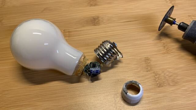
Cutting the metal screw thread revealed a plastic sleeve which insulated the circuit board from the inside of the screw.
After dismantling the lamp by carefully cutting the metal screw thread with a rotary tool, I inspected the circuit visually, with a multimeter, and with an oscilloscope. I was able to follow the PCB traces using a flashlight and magnifying glass. The PCB is generously labeled and the ICs have identifiable markings. I was unable to measure the values of the surface-mount capacitors. I was also unable to identify the component on the line input, but it's probably a PTC thermistor or similar fuse.
This lamp was more complicated than I expected. The power supply has to fit inside the screw thread of the lamp, and it uses all of the available space with a double-sided PCB and a relatively large 22µF electrolytic capacitor. It uses two separate linear LED drivers: a JW1981 and a JW16976. Most of the complexity appears to be required to support standard phase cutting (TRIAC) dimmers.
Basic Architecture
The circuit converts 120V, 60Hz AC input to pulsating DC with a diode bridge (DB). For about 40% of the duration of each pulse, input power is stored in the large electrolytic capacitor (E1), in addition to powering the LEDs. Two parallel ICs (U1 and U2) limit total current through the circuit while E1 charges. During the remaining 60% of each pulse, the LEDs are powered solely from energy stored in E1, and no current flows through the diode bridge or the ICs. Current passing through the LEDs (regardless of source) is limited by a discrete transistor (Q1), which is passively controlled with a Zener diode (D2) and a capacitor (C3).
Q1, U1, and U2 all serve to limit current. All three behave like linear regulators, meaning that they dissipate electrical energy as heat.
Steady-State Analysis
Let's begin our analysis of this lamp's normal operation by looking at the voltage across the electrolytic capacitor, E1.
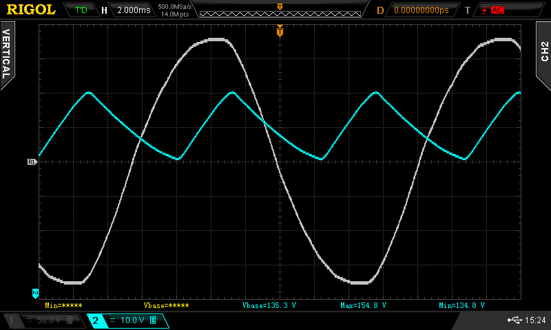
The blue trace shows the voltage across E1, which fluctuates by 20V peak-to-peak at 120Hz. Note that the blue trace is offset vertically by 135V. The white reference trace shows the AC input at 50V/div.
Remembering that the current through a capacitor is equal to its capacitance times the slope of the voltage, we can make several observations immediately:
- E1 never charges to the full input voltage. It reaches a maximum of 155V compared to the 175V at the peak of the input.
- The current through E1 reverses directions.
- E1 charges at a roughly constant current (about 135mA), even though the input voltage is sinusoidal.
- E1 discharges at a roughly constant current (about 85mA).
Next, let's look at the voltage across U1 and U2.
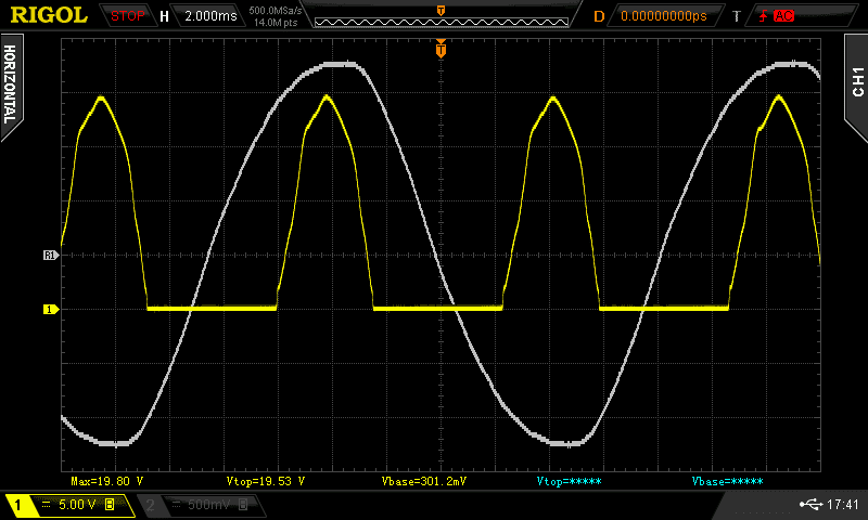
The yellow trace shows the voltage from ground to the negative terminal of E1. The white reference trace showing the AC input remains.
The voltage across the linear regulators follows the rising edge of the input sine wave while E1 charges. The voltage drop across the linear regulators has to be sinusoidal in order to produce a constant current through E1.
What happens while E1 discharges? We can see that the voltage across U1 and U2 goes to 0V, but we don't know if they are permitting any current. Although the manufacturer doesn't publish full datasheets, we can make an educated guess that RS1 and RS2 are current sensing resistors based on the naming, value, and manufacturer part summary data.
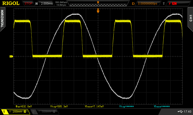
The yellow trace shows the voltage across RS2. The white reference trace showing the AC input remains.
The current through RS2 is approximately 85mA while E1 charges and 0mA while E1 discharges. (RS1 behaves identically.) We can be confident that no current flows through U1 or U2 while E1 discharges, meaning that for almost two thirds of each AC cycle, the LEDs are powered exclusively from stored energy in E1.
RS1 and RS2 each carry 85mA of current for a total of 170mA of current. We saw about 135mA of current through E1, leaving only 35mA of current through the LEDs. During E1's discharge cycle, we saw about 85mA of current, so the brightness of the LEDs must vary significantly. We will revisit this as we examine the function of Q1.
Limiting Current Through the LEDs
Like other diodes, an LED has a nearly constant voltage drop regardless of current. Connecting an LED across a constant voltage source without some form of current limiter will destroy the LED. For low-power LEDs, the usual approach is a series resistor (like in this SparkFun tutorial). However, this approach is inappropriate for high-power LEDs. A series resistor would dissipate an excessive amount of energy as heat and conduct a variable current depending on the input voltage.
Instead, this lamp uses a discrete MOSFET, Q1, to limit current through the LEDs. The gate is passively controlled by D2 (a 12V Zener diode) and C3.
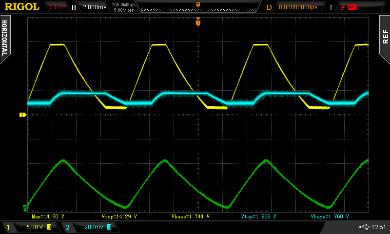
The yellow trace shows the voltage across Q1 from drain to source. The blue trace shows the voltage across Q1 from gate to source. Note that the yellow and blue traces use different vertical scales. The green trace shows the voltage across E1 at 10V/div as measured earlier.
As the voltage across E1 increases during its charge cycle, the drain-source voltage (Vds, yellow trace) across Q1 increases. When the voltage across D2 exceeds 12V (D2's Zener voltage), current flows through D2, charging the gate and C3 (blue trace) and thus increasing the current permitted through Q1. This effectively limits Vds to ~14V (D2's 12V Zener voltage plus Q1's threshold voltage).
As E1 begins to discharge, current ceases to flow through D2. Q1's gate remains at a nearly constant voltage while Vds falls. Eventually, Vds falls below Vgs and the gate charge begins to leak, causing Vgs to fall. The extra capacitance from C3 prevents the gate from discharging entirely before E1 begins charging again.
The datasheet for Q1 [1] gives a 1.3V nominal threshold voltage with limits at 1.0-2.0V. Even if the threshold is only 1V, the gate never climbs more than 900mV above threshold, while Vds never drops below 1.7V. Thus, Q1 is always in saturation and a change in the voltage across E1 has very little effect on the current permitted through Q1.
However, the current permitted through Q1 isn't exactly constant because the gate voltage varies by about 150mV. Even though there is measurable variation in the intensity of the light, at 120Hz it's imperceptible to the naked eye. We can confirm the effect is real by filming the lamp in operation using the 240FPS slow motion camera available on recent smartphones. Try it with various LED lamps around your house. Every LED lamp I filmed (regardless of brand) had a significant 120Hz flicker with the exception of a very large 80W LED fixture in my garage.
I'm unsure why this current limiting design was chosen. Would a larger value for C3 reduce the variation in current (and brightness)? Why ~14V of maximum voltage drop? Why not use an IC like U2 to more precisely control the current?
Supporting Phase-Cutting Dimmers
A warm incandescent light bulb behaves almost like a linear resistor. More voltage drives more current, which means more power and more illumination. The simplest possible dimmer would be a variable resistor wired in series with the light bulb. However, such a variable resistor would dissipate a large amount of energy as heat [2] and become hot enough to potentially start a fire.
Instead, common dimmers designed for incandescent bulbs use a semiconductor called a TRIAC to block current during a portion of the AC cycle. [3] This poses a problem for LED lamps. A standard bridge rectifier would mask the missing part of the phase up to almost 50% dimming, since the filter capacitor only draws current at the peaks of the input. If the dimmer blocks the peaks of the phase, the filter capacitor would no longer charge to its design voltage and a non-dimmable lamp would not illuminate at all.
Our driver IC needs a way to measure the percentage of the phase that is being blocked by the dimmer. This is the function of the ZVD pin on U1. D1 blocks the voltage at E1 while R3 and R4 create a voltage divider so that the voltage at ZVD is approximately 2% of the input voltage. The 170V peaks at the input will be approximately 3.33V at the ZVD pin. C1 appears to filter out high-frequency noise when the dimmer switches on.
The function of the REC pin is less obvious. It's also connected to the rectified input, but not through the voltage divider. Looking at the JW16976 description page, the manufacturer advertises a patented built-in bleeder circuit. A Google Patents search reveals the Joulwatt patent application which describes the bleeder circuit.
By design, a TRIAC begins conducting when it is triggered and continues to conduct as long as the current through the TRIAC is non-zero. With a simple resistive load, the current is zero when the input voltage crosses zero. However, this lamp only draws current during the peaks of the AC input. If the dimmer circuit only triggers the TRIAC momentarily, the lamp needs to draw a small continuous current to prevent the TRIAC from shutting off before E1 has the opportunity to charge. The REC pin is the input to the bleeder circuit and conducts current only when needed to keep the TRIAC active. The patent describes a "smart" bleeder that stops conducting current once E1 has started to charge.
Unfortunately, I didn't have a TRIAC dimmer available to capture waveforms showing U1's operation while dimmed, and I have since discarded the disassembled lamp. We can assume the current limiting circuit with Q1 would behave differently when dimmed to reduce the current through (and brightness of) the LEDs.
Conclusion
The complexity of the circuit inside this lamp surprised me. It uses three separate semiconductors (two ICs and one discrete MOSFET) to achieve almost constant current across the LED strings regardless of supply voltage. It has moderately sophisticated support for TRIAC dimmers to make it a drop in replacement for incandescent bulbs. Because it has no high-frequency switching, it has very low EMI emissions and needs no extra shielding beyond the screw thread of the bulb. The supply circuitry is so compact it fits entirely within the screw thread, making the lamp visually almost indistinguishable from an incandescent lamp. And it only cost about a dollar! I did not discover what caused the visible flickering, but I did learn much more than I expected about how LEDs have so successfully displaced incandescent lamps.
Footnotes
| [1] | Q1 is marked 6003 and is in an SOT-23-3 package. Searching for datasheets reveals matching parts made by Rectron and Shanghai Leiditech. (Based on the other components, it's reasonable to assume that this is one of the Leiditech parts.) All of the matching parts have similar threshold voltages, breakdown voltages, etc., so we don't need to worry about exactly which part it is in order to understand the circuit. |
| [2] | Let's make a rough estimate. My kitchen has six "can" lights which can each hold an 80W bulb for a total of 480W at 120V. If we want to reduce the voltage across the bulbs to only 60V, we need a voltage divider with equal resistance in the dimmer and in the bulbs. We can estimate the combined resistance of the six parallel bulbs at 30Ω (480W/120V = 4A; 120V = 4A * 30Ω). Thus, setting our dimmer to 30Ω will create a 60V drop across the dimmer and a 60V drop across the bulbs. Using Ohm's law, 60V = 2A * 30Ω, meaning that the dimmer and the bulbs will each dissipate 120W. The bulbs will be fine, but 120W of heat in an enclosed junction box will melt something. |
| [3] | If you'd like to read more about how TRIAC dimmers work, check out this article from learnabout-electronics.com or these class notes from an EE class at UT. |
